Language:


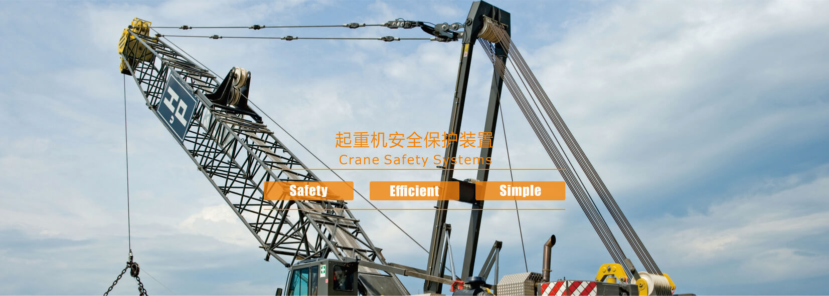
A crane load moment indicator is an integrated electronic safety system installed on cranes. Its primary function is to prevent accidents caused by crane overturning or structural damage resulting from overload or an excessive working radius.
Its fundamental design is based on a core physics principle: Moment = Weight × Working Radius.
Weight: The force exerted by the mass of the load suspended from the hook due to gravity.
Working Radius: Typically refers to the horizontal distance between the crane's pivot point and the vertical line passing through the hook (commonly known as the
Moment can be understood as the or that causes a crane to overturn. The heavier the load and the greater the radius, the larger the overturning moment generated.
The moment limiter continuously monitors the value, ensuring it remains within a safe range for the crane's current operating conditions.
A complete load moment indicator typically consists of three main components:
1. Detection Device (the system’s “senses”):
Load Cell: Typically uses a load cell or a three-pulley weight sensor to monitor the load weight in real time.
Length/Angle Sensor: Mounted on the boom to detect its elevation angle and length, enabling the calculation of the actual working radius. For tower cranes, additional sensors may also measure trolley travel.
Angle Sensor: Directly measures the angle between the boom and the horizontal plane.
Pressure Sensor: Indirectly measures the load by detecting hydraulic pressure in the hoist or boom swing circuits, commonly used in truck cranes.
2. Computational Control Unit (the system’s “brain”):
Receives data from all sensors.
Performs rapid calculations and logical judgments based on preset crane moment values, with the control unit storing the crane's load chart.
Compares the current actual moment with the rated safe moment.
3. Actuation and Alarm Devices (the system’s “hands, feet, and voice”):
The monitor displays critical information to the operator in real time, including weight, boom angle, and the percentage of the rated load.
Audible and Visual Alarm: Emits a buzzer sound and a flashing light as a warning.
Output Control Unit: This component is crucial for active protection. It can signal the crane's control system to automatically halt operations in hazardous directions.
The protection provided by the crane load moment indicator is layered and progressively escalating, acting like a strict “safety officer.”
How it works: Operators in the cab can clearly view the current load weight, actual working radius, rated lifting capacity, and torque percentage (current actual torque / rated torque × 100%) on the display.
Protective function: Provides operators with a clear, quantitative understanding of the crane's load status, preventing “gut feeling” operation and proactively avoiding accidents.
Trigger Conditions: When the moment percentage reaches 90% or 95% of the rated value (configurable).
Protective Action: The system triggers audible and visual alarms (e.g., flashing yellow warning lights and intermittent beeping) to alert the operator: “Current operation is approaching safety limits—proceed with caution!”
Purpose: To provide the operator with reaction time to halt potentially hazardous maneuvers.
Trigger Condition: When the torque percentage reaches between 100% and 105% of the rated value.
Protective Action: More urgent and intense audible and visual alarms (e.g., red lights and continuous alarm sounds). In some systems, the operating speed may be automatically restricted (e.g., reduced hoisting or slewing speed), but all operations will not be completely halted.
Purpose: To issue the highest-level warning, indicating that the crane is operating at its maximum capacity.
Trigger Condition: When the torque percentage exceeds 105% or 110% of the rated value (configurable).
Protective Action: The system's central processing unit issues commands to the control system, automatically halting or prohibiting any operations that would further increase torque.
- Prohibit hook lifting to prevent adding weight.
Prohibit boom lowering or radius reduction (prevents radius increase, as lowering the boom may actually increase the radius and torque on certain cranes).
Prohibit boom rotation toward hazardous directions, as the centrifugal force also increases the risk of tipping.
At this point, only safe operations are permitted; for example, lowering the hook to reduce the load, raising the boom to decrease the radius, or rotating toward safe directions.
Purpose: This represents the final and most critical mechanical defense. It shifts protection from “human intervention” to “technical intervention.” Even if the operator misjudges or acts recklessly, the system forcibly interrupts hazardous operations, fundamentally preventing tipping accidents.
1. Entire Crane Overturning: This represents the most severe type of accident. By keeping the moment within safe limits, the crane load moment indicator directly ensures the stability of the entire crane.
2. Boom Bending or Fracture: Overloading not only causes overturning but also subjects the boom structure to stresses that exceed its yield limit, leading to permanent deformation or fracture. The crane load moment indicator helps protect the metal structure from such damage.
3. Wire Rope Breakage: Overloading can directly cause the hoisting wire rope to snap, resulting in the load falling. The moment limiter indirectly protects the wire rope and hoisting mechanism by restricting the lifting capacity.
4. Foundation Damage: For tower cranes, excessive moments are transferred to the foundation and anchor bolts, potentially causing foundation failure. The moment limiter also helps protect the foundation's integrity.
A crane load moment indicator is not merely an “alarm device”; it is an intelligent, proactive safety system that integrates monitoring, calculation, early warning, and intervention. By combining physical principles with electronic control technology, it elevates accident prevention from operator-dependent “human safeguards”—which rely on individual experience and responsibility—to system-enforced “technical safeguards.” This significantly enhances the inherent safety of lifting operations, making it an indispensable “life-saving device” for modern cranes.
Contact: Lu
Phone: +86-18972582893
Tel: +86-0717-6746086
Email: sales@ycwpkj.com
Add: No.33 Dalian Rd,Yichang, Free Trade Zone(Hubei) China
 Lankecms
 lankecms
 wpkj01